![]() Coriolis mass flowmeters and resonant densitometers are now being manufactured on silicon microchips. While Coriolis meters have been used in high flowrate industrial fluid monitoring applications for decades, the emergence of micro-miniature Coriolis devices represents a new area of development in the flow measurement category.
Coriolis mass flowmeters and resonant densitometers are now being manufactured on silicon microchips. While Coriolis meters have been used in high flowrate industrial fluid monitoring applications for decades, the emergence of micro-miniature Coriolis devices represents a new area of development in the flow measurement category.
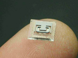
Figure 1. Micro Coriolis mass flow sensors with submillimeter to millimeter diameter tubes are now being positioned for use in a variety of industrial applications.
Making the Case for MEMS Fluid Handling
Coriolis flowmeters utilize a resonating tube, usually made of stainless steel or other corrosion-resistant metals or alloys or, in some cases, glass. Stainless steel Coriolis mass flowmeters with 12-inch diameter tubes that are several meters in length can handle flowrates up to 40,000kg/hr. Meanwhile, micro Coriolis mass flow sensors with submillimeter to millimeter diameter tubes cover the opposite end of the spectrum (Figure 1). Micro Coriolis mass flow sensors are based on MEMS (MicroElecroMechanical Systems) technology MEMS are the integration of mechanical technology elements, like sensors and actuators, with electrical elements on a common silicon or glass substrate. The small size, improved efficiency, and low cost in high volume quantities have enabled MEMS to revolutionize a variety of functional applications. Widely used MEMS sensors include pressure sensors, inertial sensors like accelerometers and gyroscopes, ink jet printer heads and optical projector display arrays. Hundreds of millions of MEMS sensors and actuators have been made in the last two decades in the automotive, medical, and consumer electronics markets. The reason for this wide adoption is not just the small size of the sensor chips, but also the method of manufacturing the sensors. As shown in Figure 2, hundreds of sensing chips are made on each wafer and batches of wafers are processed through the semiconductor wafer fan in each lot. This enables millions of individual sensors to be produced with relatively low labor content and, as a result, cost.
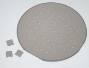
Figure 2. In the manufacture of MEMS-based Coriolis flow sensors, hundreds of sensing chips are made on each wafer and batches of wafers are processed through the semiconductor wafer fan in each lot.
Evolution of Micro Coriolis Technology
EMS-based flow sensors based on differential-pressure and thermal or hot-wire technology have been used for many years. Coriolis mass flow is the latest flow sensing methodology to employ MEMS technology. Coriolis mass flow has measurement advantages over thermal or differential-pressure flow sensors in that true mass flow outputs are obtained and a fluid density output can also be generated with the sensor. The fluid density measurement methodology is simple – the heavier or denser the fluid, the lower the resonant frequency of the fluidfilled tube. This can be used to obtain a simple density or specific gravity measurement or in a binary solution to monitor chemical concentration. The MEMS chip also has a thin-film platinum RTD temperature sensor integrated on it. This temperature-sensing capability is needed for accurate density measurements and offers mass flow, density, binary concentration and temperature sensor outputs.
At the core of the Coriolis MEMS mass flow sensor is a resonating silicon microtube (Figure 1). To begin the silicon microtube fabrication process, the inner-channel is plasma-etched into a silicon wafer. Another silicon wafer is fusion-bonded onto this. This bonding step forms the tube channel. The outer shape of the tube is next defined using photolithography and plasma etching. This silicon tube slice is then anodically bonded to a metalized glass wafer. Plasma etching sets the tube wall thickness, so high-pressure, thick-walled flow sensors can be fabricated with this process. The glass wafer has holes drilled into it that will be the fluid inlet and outlet to the resonating tube. The glass wafer is also etched prior to metal deposition and patterning such that a gap is formed between the silicon tube and the metal capacitive electrodes present on the glass surface. The metal electrodes will electrostatically drive the silicon tube into resonance and capacitively sense the frequency and twist motion of the tube. The metal layer also forms the thin-film temperature sensor and bond pads. The flow sensor microstructure now is in the form shown in Figure 1.
Figure 2 shows two products made using these chips, a Coriolis mass flow sensor (right) and the much smaller binary concentration/density sensor. To produce a flow sensor for industrial applications requires a stable output and accurate performance over a wide temperature and pressure range. The ability to measure different fluids with varying fluid densities and viscosities is beneficial. In the industrial, automotive and aerospace markets, resistance to vibration and shock is key to enabling widespread application.
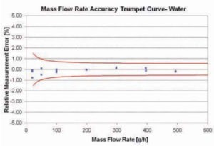
Figure 3. Flowrate measurement error versus flowrate through the sensor for a water-based application.
Performance Points
The most common measurement used to judge the point of reading accuracy of an industrial Coriolis mass flowmeter is a flowrate trumpet curve. In a trumpet curve, the relative measurement error is plotted as a function of flowrate. The outlying trumpet curve boundaries are the zero flowrate stability (0.223 g/hr) plus the 0.5 percent for a +/- 0.5 percent accurate meter. To take the mass flowrate data, a micro-scale is employed along with a timer card to independently measure the mass of liquid flowing through the sensor. Figure 3 shows the flowrate trumpet curve for the micro Coriolis sensor is within the +/- 0.5% accuracy limits for water at room temperature.
Industrial sensors must operate over a reasonable temperature range. For laboratory, micro-reactors and pilot line instruments, where the micro Coriolis flowmeter is finding its first applications, a temperature range of 15 C to 55 C is of interest. The sensor temperature is measured with the on-chip platinum thin-film temperature sensor. This sensor was successfully operated at up to 85 C without failure for prolonged periods of time. Operating temperatures can go as high as 125 C in the engine compartment and as high as 150 C when mounted on an internal combustion engine or testing petrochemicals. The upper limit on functionality was found to be the electronics, not the MEMS resonator. With upgraded electronics, these MEMS sensors have been used at temperatures as high as 160 C.
One big advantage to Coriolis mass flowmeters is that in addition to flowrate, the density of the fluid can be monitored. In a laboratory, density measurements are generally made using static fluid samples loaded with a syringe with no pressure. A number of fluids have been tested with the MEMS-based Coriolis mass flow sensor density error of five different liquids: IPA, methanol, N4 (viscosity standard), water and 30% dextrose in water. The density error was less than 0.0002 g/cc for these five fluids. Different viscosities did not affect the density or flowrate accuracy. Viscosities as high as 750 cps have been tested with this sensor with no significant mass flowrate or density error.
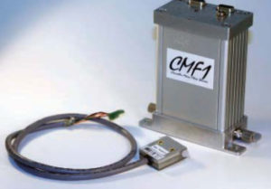
Figure 4. A Coriolis flow sensor typically used for direct methanol fuel cells in blended ethanol fuel applications.
Effects of Viscosity, High Flowrate & Chemical Reactivity
High viscosities do limit what fluids can be used with microtube sensors. Eventually the pressures needed to push a viscous fluid through a small orifice become impractical. For thick petrochemicals, users have resorted to heating the sensor to 50-70 C to enable testing of thicker fluids. Also, high flowrates can be a limit for micro Coriolis mass flow measurements, although for density or binary concentration, a bypass has been used to accommodate high flowrates. Since the microtubes are made of silicon, they cannot accommodate as wide a range of chemicals as stainless steel. These three parameters – high viscosity, high flowrates and chemical reactivity – are the primary limits for this microfluidic technology.
Pressure effects on the sensor output have also been examined. Applying 100 PSI (689 KPa) to the fluid line resulted in a density error above atmospheric pressure value of just 0.0003 g/cc for water. Burst pressure is a parameter of interest for industrial applications. The burst pressure of the microtubes used to produce this Coriolis mass flow sensor was found to be in the 1,100 PSI to 1,300 PSI range.
Since all Coriolis mass flowmeters are vibratory devices, vibration sensitivity has been an underlying problem with this technology. This is a critical problem for industrial, automotive, and aerospace applications where shock and vibration are commonplace. Conventional metal tube Coriolis mass flowmeters resonate at 100 Hz to 1,500 Hz, leaving them susceptible to the spectrum of common external mechanical vibration and shock frequencies, which are under 2,000 Hz.
To examine the difference between the MEMS sensor in this study and a conventional steel tube and MEMS-based Coriolis mass flow sensor, both were placed on a vibratory test stand and cycled from 10 Hz to 1,000 Hz, starting at 0.5 g and going to 2 g acceleration while monitoring the zero flowrate output of a water-filled tube. The conventional low-flowrate, steel Coriolis meter had both large flow and density output spikes at its resonance frequency at very low accelerations, 0.5 g. The silicon tube used in the MEMS sensor in this study had resonant frequencies ranging from 20 KHz to 30 KHz, well above what is typically experienced in industrial, automotive, or aerospace applications.
The zero flowrate output of the MEMS tube was within a +/- 1 g/hr band at all external vibrational frequencies at 2 g. The density output was not affected by vibration on the MEMS sensor. This is an advantage for the MEMS-based Coriolis mass flowmeter over conventional technology and can broaden the field of use to include applications with significant vibration. As such, these MEMS-based Coriolis mass flowmeters would seem to be a good fit for vehicles, mounted on moving platforms and robotic pipette systems undergoing constant start and stop motion.
Emerging Applications
Some of the emerging applications for this technology are chemical concentration, including alcohol to water concentrations in fuel cells and ethanol to gasoline concentrations in ethanolblended fuels in automobiles. Small MEMS-based sensors are a good fit for portable applications like fuel cell-powered laptop computers, where an optimized water-to-methanol concentration is needed to reduce membrane crossover and optimize the efficiency of the fuel cell.
The smaller sensor in Figure 4 is widely used in direct methanol fuel cells. For ethanol-blended fuels, the sensor lets the engine control module know the gasoline-to-ethanol ratio to maintain optimum operating conditions. Other applications for Coriolis mass flow and density sensors exist in the pharmaceutical, microreactors, biomedical, nuclear, perfume, petroleum and beverage industries, as well as in distilleries, hematology and urology. The device can also be used to measure proof, ºBrix, ºPlato and API gravity. The beverage industry uses the meter for determining the sucrose, alcohol and extract percentages. Since distilleries are taxed based on alcohol content, measurement accuracy is of great importance. MEMS-based Coriolis mass flow sensors have been applied to the medical field in the area of drug infusion monitoring and pumping. The Coriolis effect, which causes the tubes to twist under flowing conditions, is sensed capacitively on the microchip. An FDA-approved drug flow monitor uses a chip to measure drug flowrates and the total volume of infused drugs into a patient in the 5 mL/hr to 200 mL/hr flowrate range. The IV line from gravity-fed IV bags are connected in series with the small flow sensor to provide an extra layer of protection to the patient and reduce the incidence of drug-infusion errors.