Abstract
![]() This article examines the use of a micromachined resonating tube to measure both the dynamic viscosity and density of a fluid enabling the calculation of the kinematic viscosity. Dynamic viscosity is measured using the damping effect that a fluid has on the motion of the resonating tube. Fluid damping requires a change in drive voltage to maintain a constant vibrational amplitude. The density is measured via the change in resonant frequency caused by a change in fluid density while the viscosity is measured by monitoring the peak signal of the resonator. The dynamic viscosity measurement error between the new sensor and the calibration references ranges from 0.006 to 0.15 cP, or 0.6 to 8%. A variety of applications for the sensor will be discussed.
This article examines the use of a micromachined resonating tube to measure both the dynamic viscosity and density of a fluid enabling the calculation of the kinematic viscosity. Dynamic viscosity is measured using the damping effect that a fluid has on the motion of the resonating tube. Fluid damping requires a change in drive voltage to maintain a constant vibrational amplitude. The density is measured via the change in resonant frequency caused by a change in fluid density while the viscosity is measured by monitoring the peak signal of the resonator. The dynamic viscosity measurement error between the new sensor and the calibration references ranges from 0.006 to 0.15 cP, or 0.6 to 8%. A variety of applications for the sensor will be discussed.
Introduction
Viscosity is often thought of as the fluid’s friction, resistance to flow or the fluid’s resistance to shear when the fluid is in motion. The viscosity of a fluid is often represented as a coefficient, which describes the diffusion of momentum in the fluid. The measure-ment of viscosity has been employed for many decades to monitor and test lubricants, blood, mucus, adhesives, paints, fuels and other fluids [1-5]. Viscosity measurements have been made using capillary force, falling balls, moving paddles and vibrating tuning forks. Several small standing acoustic wave (SAW) and microelectromechanical systems (MEMS) viscometers have been developed in recent years [3-7].
Micromachined resonating tubes have been used to measure mass flow, density and chemical concentration [8-11]. Fig. 1 shows a photograph of such a microtube. This paper will show that a res-onating microtube can be used to measure both the density and viscosity [12] of a fluid. The kinematic viscosity u (cSt or mm2/s) of a fluid is given by the expression:
v = n/p
where the n is dynamic viscosity (cP or mPa s) and p is the density (g/cm3) of the fluid.
The density of a liquid p is given by the expression:
p = 1/V {(Ks / 4n2f2) – m}
where vV is the internal volume of the resonant tube, mt is tube mass, K, is the spring constant of the tube and f is the resonance frequency of the tube. As can be seen by the expression above, the density is inversely proportional to the square of the resonance frequency. Results for density measurements made with a microtube have been published previously [8,10,11]. The damping of the resonator can be used to measure dynamic viscosity. By measuring both the density and dynamic viscosity the kinematic viscosity can be calculated. The ability to measure these three fluid parameter, as well as temperature and mass flow rate is a unique capability for a single microfluidic chip.
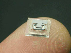
Fig 1. – The microfluidic chip with resonating microtube.
Experimental Procedures
The resonant microtubes used in this paper employ a MEMS fabrication process, which uses a combination of plasma and wet etching, photolithography, along with wafer bonding to form their microfluidic chips 110,13]. The sensors produced with this process employ a chip-level, vacuum package to reduce external damping of the resonator. Fig. 1 shows an uncapped microtube resonator chip. Fig. 2 shows a side-view drawing illustrating the position of the resonator, underlying metal electrodes, holes and vacuum cavity. The silicon tube is anodically bonded to glass (Pyrex). This glass wafer has metal electrodes, a thin-film temperature sensor and runners used to carry electrical signals. Two holes in the bottom glass chip admit fluid into the silicon microtubes. The tube is driven into resonance electrostatically and its motion sensed capacitively using metal electrodes under the tube and accompanying electronic circuits connected to the MEMS chip via wire bonding. Fig. 3 shows a photograph of the packaged sensor. The output of the MEMS resonator is buffered, amplified and processed by the electronics shown on the printed circuit board in Fig. 3.
| Liquid | Pref(g/cm3) | nref(cP) | vref(cST) |
|---|---|---|---|
| S3 | 0.8644 | 3.531 | 4.085 |
| N1 | 0.7267 | 0.8602 | 1.184 |
| N2 | 0.7877 | 2.087 | 2.650 |
| N4 | 0.7879 | 4.580 | 5.773 |
NIST certified density/viscosity calibration standards (labeled 53, N1, N2 and N4), purchased from Cannon Instruments Company, were used in this investigation. Table 1 lists the properties of these standards at 25 °C. In addition other liquids such as Dextrose (sugar) solutions in water, IPA (isopropyl alcohol), methanol and degassed, deionized water were first tested in a Brookfield DV-I viscometer and Anton Paar 4500 density meter and/or the density and viscosity values were obtained from the literature [ 14] for pure fluids. The density and viscosity values obtained with the sensor described in this paper were compared to the calibration standards and to data taken from these other laboratory instruments.The majority of the tests were done at room temperature but a few samples were cooled or heated using an attached Peltier panel.
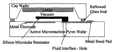
Fig 2. – A side-view diagram of the MEMS chip, showing the resonating tube over the meter electrodes and vacuum chip-level packaging.
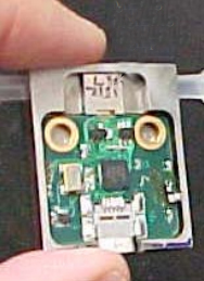
Fig. 3 – The packaged, MEMS-based viscosity sensor.
Results
Just as external gas molecules can dampen a resonator, so can fluid within a resonating tube can dampen motion. To experimentally examine this relationship, the peak amplitude or gain of the resonator was monitored for different flu ids. Fig. 4 shows how the amplified gain, in terms of peak signal voltage out divided by the drive voltage applied to the resonator, varied for a variety of fluids tested at room temperature (25-29 °C). The system maintains a constant output voltage, so damping from the liquid requires an increase in the drive voltage. The more viscous fluids such as standard N4 and Dextrose solutions dampen the resonator microtube resulting in a lower gain than less viscous fluids like water and methanol.
This type of resonator data for several fluids was used to develop a dynamic viscosity output for the sensor shown in Fig. 3. Table 2 lists the experimental data taken for density and viscosity along with reference data. Since there was some variation in the test temperature, there rs some variation in the reference data (14] as well as experimental data. The kinematic viscosity values listed in Table 2 are obtained by using the sensor density and dynamic viscosity data and Eq. (1).
The samples sizes for Table 2 data ranged from 92 to 804 readings per liquid. The standard deviations for density ranged from 0.00003 to 0.00011 g/cm3 and for viscosities from 0.014 to 0.025 cP for both the_experimental data and reference data over the temperature variation of the tests. Good agreement is found between measurements and reference data for the density and dynamic viscosity. The error from the references in n ranges from 0.006 to 0.15 cP, or 0.6 to 8%. Figs. 5 and 6 plot the dynamic viscosity with error observed with the new MEMS-based meter as with respect to several different fluids and then viscosities in the 0. 5 – 6 cP range.
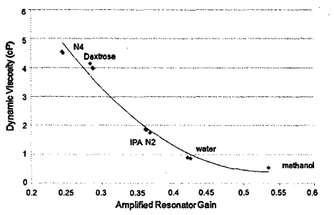
Fig 4. – The amplified resonator gain at room temperature as a function of viscosity for a variety of fluids.
Discussion and Future Applications
Conventional viscometers [1,2) measure only the viscosity of a fluid. A second test system such as a densitometer or literature data for density is required to calculate the kinematic viscosity. Kinematic viscosity is the preferred measurement for lubricants and other applications [15). A meter that can simultaneously measure flu id density and dynamic viscosity and then calculate kinematic viscosity offers advantages in areas in which kinematic viscosity is most important. In future work a wider range of viscosities will be examined, the 0.5-6 cP range examined in the current study covers the applications of solvents, intravenous solutions and drugs, beverages and light fuels. A density meter based on this technology (10j has already found use with thicker liquids. The capability to test higher viscosities will allow more petrochemicals and lubricants to be monitored with this new device.
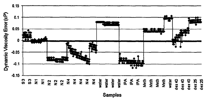
Fig 5. – A plot of dynamic visocity error for the various samples tested.
| Liquid | T(degrees C) | p (g/cm3) | pref (g/cm3) | n (cP) | nref (cP) | v (cST) |
|---|---|---|---|---|---|---|
| S3 | 9.71-9.73 | 0.8750 | 0.8749 | 5.527 | 5.576 | 6.316 |
| N1 | 15.0-19.8 | 0.7321 | 0.7324 | 0.894 | 0.965 | 1.221 |
| N2 | 29.4-29.7 | 0.7837 | 0.7844 | 1.747 | 1.898 | 2.230 |
| N4 | 28.4-28.7 | 0.7854 | 0.7855 | 4.030 | 4.150 | 5.130 |
| Water | 25.4-25.5 | 0.9969 | 0.9969 | 0.866 | 0.861 | 0.868 |
| IPA | 25.8-25.9 | 0.7808 | 0.7805 | 1.866 | 2.026 | 2.389 |
| Methanol | 25.6-25.7 | 0.7871 | 0.7871 | 0.542 | 0.570 | 0.688 |
| Dex40% | 25.4-25.5 | 1.1610 | 1.1610 | 4.529 | 4.570 | 3.901 |
| Dex25% | 25.2-25.3 | 1.1009 | 1.1003 | 2.235 | 2.220 | 2.030 |
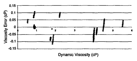
Fig 6. – A plot of dynamic viscosity error for a range of dynamic viscosities measured.
Chemical concentration and density meters made with these MEMS devices have been shown to function well a higher temperatures, 90-150 °C (10,16J. Additional work to push the temperature range of use for the MEMS viscometer will also be undertaken. Like density and chemical concentration, viscosity is a fluid parameter that does not require testing the entire fluid stream. Many viscometers test batch samples, limiting their usefulness in industrial and remote applications. Bypass fluidic packages already developed for the MEMS density chips [17] could be employed to monitor the viscosity in large flow rate, inline systems. Fig. 7 shows one bypass package design for this sensor. A high temperature density and kinematic viscosity sensor that is MEMS-based may find applications in oil quality sensing for large-volume automotive applications. The microtube described in this paper has an on-chip thin-film temperature sensor and has been used to make Coriolis mass flow sensors [11 ]. Viscosity measurements have been made while taking mass flow rate data with the same resonating microtube
device.
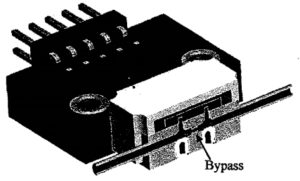
Fig 7. – Cut-away diagram of a bypass package for the microfluidic viscosity and density sensor.
Conclusions
This article covered the use of a micromachined resonating tube to measure both the dynamic viscosity and density of a fluid enabling the calculation of the kinematic viscosity. Dynamic viscosity is measured using the damping effect that a fluid has on the motion of the resonating tube. Damping requires a change in drive voltage to maintain a constant vibrational amplitude. The density is measured via the change in resonant frequency caused by a change in fluid density. The dynamic viscosity measurement error between the new sensor and the calibration references ranged from 0.006 to 0.15 cP, or 0.6 to 8%. A variety of sensor applications and future improvements for the sensor were discussed. The ability to measure these three fluid parameter, as well as temperature is a unique capability for a single microfluidic chip.
Acknowledgement
The authors would like to acknowledge the Michigan Economic Development Corporation (MEDC) for partial financial support of this project.