Abstract
![]() A microfluidic Coriolis mass flow sensor is discussed. The micromachined flow sensors are made using silicon tubes bonded onto a metalized glass substrate. True mass flow rates with better than +/- 0.5% accuracy were measured between 1 g/hr to 500 g/hr. The sensor also provides a temperature and density output. The sensor output was resistant to pressure, temperature, vibration fluid density and viscosity. Unlike conventional steel Coriolis mass flow meters, MEMS-based sensors are immune to external vibration. Applications for these low flow rate devices includes, chemical mixing, additives, biotechnology, chromatography, pharmaceutical development and other areas where extremely small volumes of liquids are mixed, studied or metered and where shock and vibration are encountered.
A microfluidic Coriolis mass flow sensor is discussed. The micromachined flow sensors are made using silicon tubes bonded onto a metalized glass substrate. True mass flow rates with better than +/- 0.5% accuracy were measured between 1 g/hr to 500 g/hr. The sensor also provides a temperature and density output. The sensor output was resistant to pressure, temperature, vibration fluid density and viscosity. Unlike conventional steel Coriolis mass flow meters, MEMS-based sensors are immune to external vibration. Applications for these low flow rate devices includes, chemical mixing, additives, biotechnology, chromatography, pharmaceutical development and other areas where extremely small volumes of liquids are mixed, studied or metered and where shock and vibration are encountered.
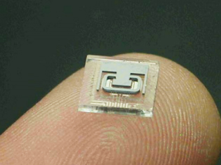
Fig 1. The microfluidic chip and resonating microtube.
Introduction
The majority of MEMS-based flow sensors employ volumetric flow measurement methods such as thermal hot wire sensors [1,2]. The advantages of a Coriolis mass flow sensor [3-9) over other methods include the ability to measure true mass flow regardless of the fluid going through the resonating tube. Coriolis mass flow technology also provides a fluid density output which can be used for fluid identification, concentration measurement and quality monitoring. Conventional Coriolis mass flow sensors [8,9) have been commercially available for over 30 years. These flow meters generally employ large diameter stainless steel tubes. Unlike steel tube meters which are fabricated one at a time, MEMSbased sensors [3-7] employ wafer fabrication enables hundreds of micromachined silicon Coriolis mass flow tubes and even assembled subsystems to be produced with one wafer stack. This batch fabrication method reduces the manufacturing costs enabling a wider use of Coriolis mass flow technology.
The basic function of an ideal resonating Coriolis mass flow sensor can be expressed by the following equations. The mass flow rate q is given by:
q = Ks9/(4wLr)
Where, Ks angular spring constant of the flow tube, 9 is the twisting angle of the tube, w is the resonance frequency, L is the length of the tube and r is the radius of the U-bend of the tube. Therefore, the mass flow rate is directly proportional to the twisting angle and inversely proportional to the resonance frequency. The density of a liquid p is given by the expression:
p = 1/V [(K8/4n2f2) -m1]
where V is the internal volume of the resonant tube, m1 is tube mass, Ks is the spring constant of the tube and f is the resonance frequency of the tube. As can be seen by the expression above, the density is inversely proportional to the square of the resonance frequency.
Any process requiring the metering or mixing of small amounts of liquids or gases such as semiconductor doping, leak detection, cleaning chemicals, additives, pharmaceutical formulation, fragrance and flavor additions can benefit from this technology. Precise mixing requires the measurement of true mass flow, not an estimate based on a volumetric measurement. The performance of a MEMS-based Coriolis mass flow sensor, designed for industrial applications will be covered in this paper.
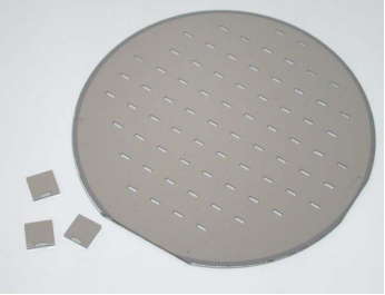
Fig. 2. A micromachined wafer stack, enabling chipscale vacuum packaging.
Micromachined Coriolis Mass Flow Sensor Fabrication
Micromachined or microfluidic Coriolis mass flow sensors have been developed in the last decade [3-7]. Coriolis mass flow sensors offer advantages over hotwire and pressure-based flow sensors such as measuring true mass flow regardless of fluid, providing a density and temperature output and not heating the fluid under test.
Enoksson et al. [3] at the Swedish Royal Institute of Technology, conducted research into fabricating a micromachined Coriolis mass flow sensor using a wet etched silicon tube formation process, which was anodically bonded to glass. The silicon tubing was hexagonal in cross-sectional shape with a 1mm outer diameter. The tube itself was driven into resonance electrostatically by an external electrode 30 microns from the tube and had a resonant frequency of9.4- 9.9KHz. An excitation voltage of lOOV was applied to the structure. The tube motion was sensed optically by focusing a laser on the loop shaped portion of the tube. The reflected beam was detected using a two dimensional high-linearity position detector. This silicon chip was attached to a brass package which had metal tubing attached for the fluidic interface. The optical sensing apparatus was external to the brass package. Flow rates down to 360 g/hr of water flow were measured, with good bi-directional linearity being obtained for both water and methanol.
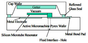
Fig. 3. A side-view diagram of the MEMS chip, showing the resonating tube over the metal electrodes and vacuum chip-level packaging.
More recently another academic group at the University ofTwente made a MEMS-based Coriolis mass flow tube using very thin (1.2um) CVD silicon nitride walls [7]. This sensor was capable of measuring flow and density of liquids and gases. It resonated at 2 -3 KHz and used a laser reflectance to make flow sense measurements on the dielectric tubes.
Integrated Sensing Systems, Inc. (ISS) published it first paper in 2001 on a micromachined Coriolis mass flow sensor [4]. The microfluidic flow sensor, which is covered in this paper, employed a plasma etched defined silicon tube, mounted to a metalized glass substrate with a very narrow capacitive gap [5,6]. To date, published work on MEMS Coriolis mass flow studies [3,4], [7] entailed the development of an R&D micromachined chip only, and employed a laboratory vacuum chamber and instrumentation to both enable and sense resonance. Further work was needed to transform this technology into an industrial product.
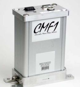
Fig. 4. Final packaged MEMS-based, industrial Coriolis mass flow sensor.
At the core of the MEMS flow sensor covered in this paper is a resonating silicon microtube, shown in Fig. 1. To begin the tube fabrication process the inner channel is plasma etched into a silicon wafer. Another silicon wafer is fusion bonded onto this. This bonding step forms the tube channel. The outer shape of the tube is next defined using photo lithography and plasma etching. This silicon tube slice is then anodically bonded to a metalized glass wafer. Plasma etching sets the tube wall thickness, so high pressure, thick walled flow sensors can be fabricated with this process. The glass wafer has holes drilled into it that will be the fluid inlet and outlet to the resonating tube. The glass wafer also is etched prior to metal deposition and patterning such that a gap is formed between the silicon tube and the metal capacitive electrodes present on the glass surface. The metal electrodes will electrostatically drive the silicon tube into resonance and capacitively sense the frequency and twist motion of the tube. The metal layer also forms the thin film temperature sensor and bond pads. The flow sensor microstructure now is in the form shown in Fig. 1.
To push this technology into a useful form, chip-level vacuum packaging of the resonant tube was employed. A quality factor or Q value of the resonator above l 000 was desired to obtain sufficient signal to noise ratio and frequency I density resolution with the sensor. Initial test data on R&D samples were made using a vacuum chamber to obtain the low pressures required to reduce damping that occurs with gas molecules and the closely positioned resonator and opposing metalized glass surface. From the data taken in the laboratory system it was observed that a pressure of under lOOmTorr (0.01 KPa) would be needed to obtain a useful signal. Chipscale vacuum packaging is most often accomplished using wafer to wafer vacuum bonding. Fig. 2 shows an example of a bonded wafer stack. After wafer bonding the individual chips are singulated by sawing the wafer. Conventional glass frit and solder sealing produces cavity pressures of 1-2 Torr (0.101 – 0.202 KPa) [IO]. For this rnicrofluidic flow device, a cavity pressure of 1.4 Torr was obtained with glass frit sealing and due to squeeze-film damping and molecular interaction, the Q value was limited to 40 for this wide vertical resonator and narrow (<5 micron) gap. To overcome the pressure limitation of conventional vacuum wafer bonding a reactive gettering material [ 11] was integrated into the wafer fabrication process. A capping wafer, generally either silicon or glass is patterned and etched to form the cavity that encloses the active micromachine and opens up access to the electrical wirebond pads. At this point a thin film metal getter is applied and patterned on the top portion of the cavity. This micromachined capping wafer is bonded to the glass wafer using a reflowed glass, as shown in Fig. 3.
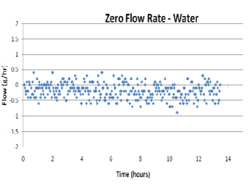
Fig. 5. The output of the flow sensor, with no flow, filled with water at room temperature.
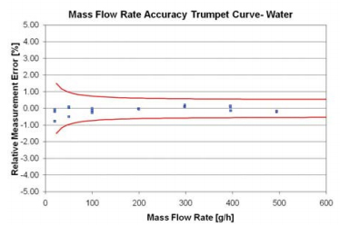
Fig. 6. Flow rate measurement error versus flow rate through the sensor for water.
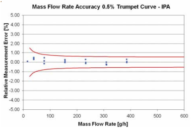
Fig. 7. Flow rate measurement error versus flow rate through the sensor for water.
Through wafer-to-wafer bonding with getters, the vacuum level obtained was found to be under a milliTorr, resulting in Q values ranging from 10,000 to 61 000 for the silicon tube resonator. These tubes are el;ctrostatically driven into resonance with less than a 5V bias as the tube motion is sensed capacitively. Extensive life testing of the hermetic glass frit seal and getter has been performed to insure that the basic MEMS device is reliable [12]. These high Q values for resonant systems are rarely seen in the macroscopic world.
A platinum resistive temperature sensors has also been integrated into the microfluidic chip [7]. This element is located just a few micro from the silicon fluid conduit and so gives the chip a very quick temperature response. The microfluidic device, like conventional Coriolis mass flow meter, can measure mass flow, density and temperature. The technology has been used to produce standalone density and chemical concentration meters that began seeing commercial use in laboratory and industrial applications [13].
For industrial Coriolis mass flow applications a robust mechanical housing was used to enclose the MEMS sensor and printed circuit boards used for signal processing. The flow sensor is shown in Fig. 4. The sensor has a 5V power supply and a digital RS-232 output. The fluid ports are stainless steel 10-31 UNF fittings.
To produce a flow sensor for industrial applications requires produce stable a flow output, sensor for accurate industrial performance applications on a wide measure temperature different and fluids pressure with varying range. The ability to measure different fluid densities to and viscosities is beneficial. In the industrial, automotive and aerospace markets, resistance and vibration and shock is key to finding a wide spread application.
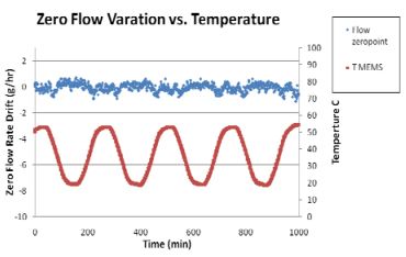
Fig. 8. Zero flow rate (top) versus temperature (bottom) and time for water.
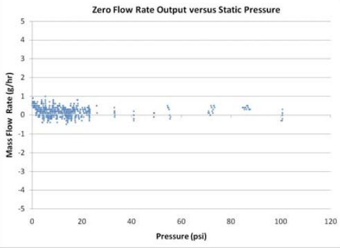
Fig. 9. Zero flow rate measurement error versus static pressure for water.
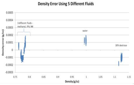
Fig. 10. The density error of five liquids.
The zero now rate stability is the most basic parameter used to evaluate the resolution and accuracy capability of a flow sensor. It is generally more sensitive to accuracy and resolution problems in a sensor than measurements taken at high now rates. Fig. 5 shows how the zero mass flow rate output varied over more than I 2 hours at room temperature. The majority of the data points are within +/- 0.5 g/hr. The standard deviation of the zero rate now output was 0.223 g/hr, which can be used to represent the zero Oow· rate stability of the sensor.
The most common measurement used to judge the point of reading accuracy of an industrial Coriolis mass flow meter is a flow rate trumpet curve. 1n a trumpe, curve the relative measurement error is plotted as a function of now rate. The outlying trumpet curve boundaries are the zero now rate stability (0.223 g/hr) plus the 0.5% for a+/- 0.5% accurate meter. To take the mass flow rate data a Sartorius microscale was employed along with a National Instruments timer card to independently measure the mass of liquid flowing through the sensor. Figure 6 shows that the flow rate trumpet curve for the microCoriolis sensor developed is within these+/- 0.5% accuracy limits for water at room temperature. Fig. 7 shows the trumpet curve for isopropyl alcohol (IPA) flowing through the meter. The data points in fig. 6 and 7 are for three different excursions through the O to 500 g/hr now rate range. As is commonly done, the maximum now rate (500 g/hr) for a now sensor trumpet curve like those in Fig. 6 and 7, was the point at which the back pressure of the flow sensor reached I atm (101 g/hr). The meter was able to measure flow rates up to 1000 g/hr, but had back pressures higher than 101KPa at these high flow rates.
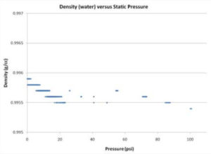
Fig. 11. Density variation due to static line pressure.
It should be noted that the density and viscosity of IPA is significantly different than water at room temperature: for example, at 20’C, water density = 0.9982 g/cc and viscosity= 1.0 cps, IPA density=0.7851 glee and viscosity= 2.4 cps. A thermal flow sensor would require recalibration to accurately measure mass flow rates of different fluids of widely varying properties. This insensitivity to fluid parameters in accurately measuring mass flow rates without recalibration is an advantage for Coriolis mass flow measurement systems. This easily enables industrial users to switch fluids through the same flow sensor without a loss in accuracy.
Industrial sensors must operate over a reasonable temperature range. For laboratory and pilot line instruments, where the meter is finding its first applications, a temperature range of 15’C to 55’C is of interest. Fig. 8 shows the zero flow rate sensor output as the temperature was cycled repeatedly. The sensor was filled with water for this test, the lower curve in Fig. 8 is the temperature measured with the on-chip platinum thin film temperature sensor. The top set of data points is the zero flow rate output, which was within a +l-1 g/hr range. This sensor was successfully operated at up to 85’C without failure for prolonged periods of time.
For many industrial applications the line pressure that the flow sensor will experience will vary. For very thin MEMS Coriolis tubes [7], pressure variation could be a problem since the stiffness of the tube will change with pressure resulting in a frequency shift, this happens even with thick metal tubes [8]. Low burst pressure is another problem with very thin microtubes. The silicon microtubes described in this paper can have virtually any wall thickness. Density sensitivity limits the upper end of what tube wall thickness should be employed. Fig. 9 shows that for the existing silicon microtubes that essentially no changes in the zero flow rate output for water was noted up between O and 100 psi (689 KPa ).
One big advantage to Coriolis mass flow meters is the density output that is available. In a laboratory, density measurements are general made using static fluid samples loaded with a syringe with no pressure [13]. A number of fluids have been tested with the MEMS-based Coriolis mass flow sensor. Fig. 10 shows the deviation from the reference density value or density error of five different liquids: IPA methanol N4 (viscosity standard), water and 30% dextrose in water The density error was less than 0.0002 glee for these
five fluids. It should also be noted that the liquids used to generate Fig. 10 had differing viscosities ranging from 0.586 cps for methanol up to 5.2 cps for N4.
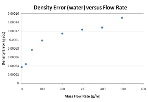
Fig. 12. Density output measurement error versus flow rate through the sensor for water.
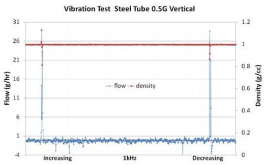
Fig. 13. Zero flow rate measurement error of a conventional steel tube Coriolis mass flow sensor versus vibrational frequency at 0.5 g, for water.
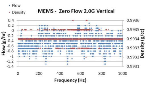
Fig. 14. Zero flow rate measurement error versus vibrational frequency at 2 g, for water.
These different viscosities did not affect the density or flow rate accuracy. Viscosities as high as 750 cps have been tested with this sensor with no significant mass flow rate or density error. The density output error for water at room temperature as a function of static pressure is shown in Fig. l l. Applying l 00 psi (689 KPa) to the fluid line resulted in a density error above atmospheric pressure value of just 0.0003 glee for water. Burst pressure is a parameter of interest for industrial applications. The burst pressure of the microtubes used to produce this Coriolis mass flow sensor was found to be in the 600 psi (4136 —KPa) to 750 psi (5171K.Pal_ -range. Burst pressure can be varied via tube wall thickness changes. Next the density error associated with flow rate was examined. Fig. 12 shows the density error for water across the 0 to 500 g/hr flow rate range of the sensor was under 0.00015 g/cc for all flow rates from 0 to 500 g/hr.
Since all Coriolis mass flow meters are vibratory devices, vibration sensitivity has been underlying problem with this technology. This is a critical problem for industrial, automotive and aerospace applications where shock and vibration are common place. Conventional metal tube Coriolis mass flow meters resonate at 100 to 1500 Hz [8,9], leaving them susceptible to the spectrum of common external mechanical vibration and shock frequencies which are under 2000 Hz. To examine the difference between the MEMS sensor in this study and a conventional steel tube and MEMS-based Coriolis mass flow sensor both were placed on a vibratory test stand and cycled from 10 Hz to 1000 Hz starting at 0.5 g and going to 2 g acceleration while monitoring the zero flow rate output of a water filled tube. Figure 13 shows that the conventional low flow rate, steel Coriolis meter had both large flow and density output spikes at its resonance frequency at very low accelerations, 0.5 g. The silicon tube used in the MES sensor in this study has resonant frequencies ranges from 20K.Hz to 30K.Hz, well above what is typically experienced in an industrial, automotive or aerospace applications. Fig. 14 shows that the zero flow rate output of the MEMS tube was within a +/-1 g/hr band. The density output was not affected by vibration as well as the MEMS sensor. This is an advantage for the MEMS-based Coriolis mass flow meter over conventional technology and can broaden the field of use to include applications with significant vibration. These MEMS-based Coriolis mass flow meters can be used on vehicles, mounted on moving platforms and robotic pipette systems undergoing constant start and stop motion.
Conclusions
A microfluidic Coriolis mass flow sensor, hardened for industrial applications, was discussed. The micromachined flow sensors are made using silicon tubes mounted onto a metallized glass substrate. True mass flow rates with better than +/-0.5% point of
reading accuracy were measured between 1 g/hr to 500 g/hr. In-line density accuracy of better than 0.0003 g/cc was observed over a variety of test conditions. The mass flow and density sensor output was resistant to pressure, temperature, vibration fluid density and viscosity. Applications for these low flow rate devices exist is, chemical mixing, perfumes, flavors, pharmaceutical development and other areas where extremely small volumes of liquids are mixed, studied or metered.
Acknowledgements
The authors would like to acknowledge the financial support of the Michigan Economic Development Corporation.